
- Replacing clutch disk
-

REMOVAL
WARNING:
* Make sure jacks and safety stands are placed properly, and hoist brackets are attached to correct position on the engine.
* Apply parking brake and block rear wheels so car will not roll off stands and fall on you while working under it.
CAUTION: Use fender covers to avoid damaging painted surfaces.
1. Disconnect the negative (-) cable first, then the positive (+) cable from the battery.
2. Drain transmission oil.
3. Remove the intake air tube, intake air duct and air cleaner housing assembly.
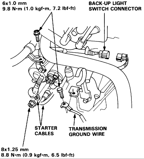
4. Disconnect the starter motor cables, transmission ground wire and back-up light switch connector.
5. Remove the wire harness clamps.
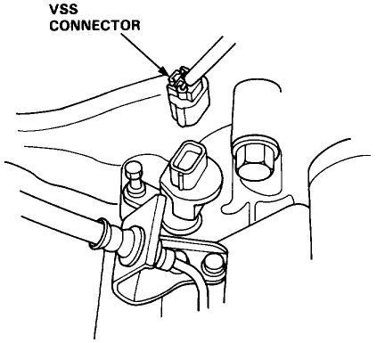
Disconnect the Vehicle Speed Sensor (VSS) connector.
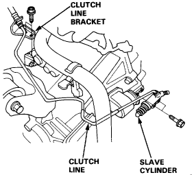
7. Remove the clutch line bracket, clutch line clamp, and slave cylinder. CAUTION:
o Do not operate the clutch pedal once the slave cylinder has been removed.
o Take care not to bend the clutch line.
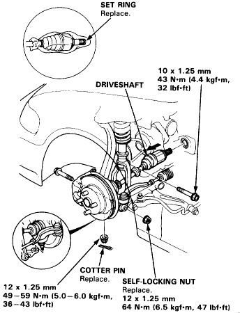
Remove the driveshafts. NOTE: Coat all the precision finished surfaces with clean engine oil or grease.
Tie plastic bags over the driveshaft ends.
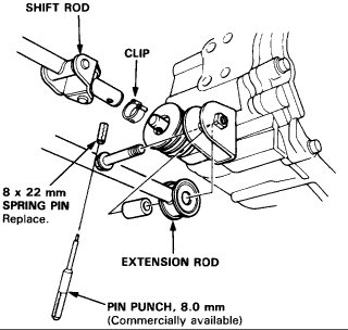
Remove the shift rod and extension rod.
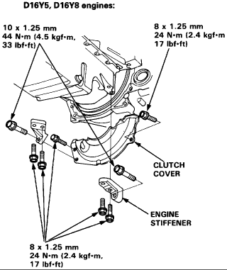
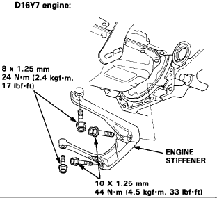
Remove the engine stiffeners and clutch cover.
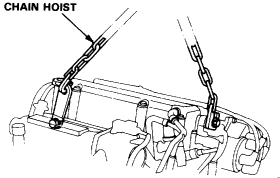
12. Install the bolts in the cylinder head and attach a chain hoist to the bolts, then lift the engine slightly to unload the engine and transmission mounts.
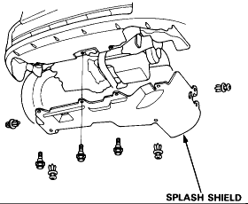
Remove the splash shield.
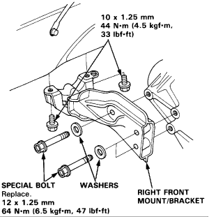
14. Remove the right front mount/bracket.
15. Place a jack under the transmission.
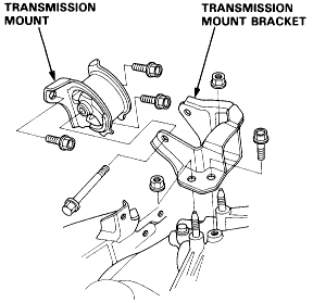
Remove the transmission mount bracket and mount.
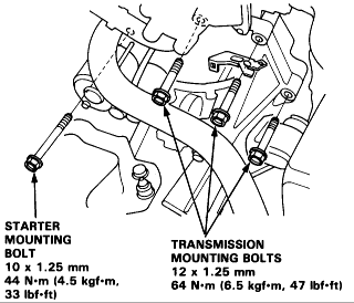
Remove the three upper transmission mounting bolts and the lower starter mounting bolt.
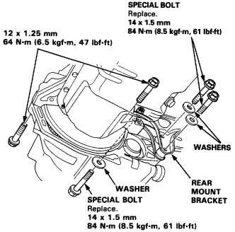
18. Remove the rear mount bracket bolts and transmission mounting bolts.
19. Pull the transmission away from the engine until it clears the mainshaft, then lower it on the transmission jack. CAUTION: Take care not to bend the clutch line.
Level Transmission and Drivetrain Clutch Service and Repair Clutch Replacement
Clutch Replacement
Notes
1. Remove transaxle as described under Manual Transmission/Transaxle.
2. Remove release bearing as follows:
1. Remove boot from clutch housing.
2. Remove release fork from clutch housing by squeezing release fork set spring with pliers.
3. Check release bearing for excessive play and roughness, then replace if necessary.
4. Measure diaphragm spring fingers height using special clutch alignment disc and shaft tool Nos. 07JAF-PM7001A, 07JAF-PM7012A and 07936-3710100, or equivalents. Standard is 0.03 inches.
5. If height exceeds 0.04 inch, replace pressure plate.
6. Lock flywheel with a special ring gear holder tool No. 07LAB-PV00100, or equivalent, then install special clutch alignment shaft tool Nos. 07JAF-PM7012A and 07936-3710100, or equivalents.
7. Loosen pressure plate attaching bolts in crisscross pattern, one turn at a time to prevent warping pressure plate, then remove pressure plate.
8. Inspect pressure plate surface for wear, cracks and burning, then check warpage. Standard new warpage is 0.001 inches.
9. If pressure plate warpage exceeds 0.006 inch, replace.
10. Remove clutch disc from flywheel and special tools.
11. Inspect clutch lining for signs of slippage and oil, replace if burned black or oil soaked.
12. Measure clutch disc thickness. Standard new is 0.33-0.36 inches; service limit is 0.24 inches.
13. Measure depth from lining surface to rivets on both sides. Standard new is 0.05 inches; service limit is 0.01 inches.
14. Spin release bearing by hand and check for excessive play. Do not wash bearing in solvent .
15. Inspect flywheel teeth for wear and damage, then check mating surface for wear, cracks and burning.
16. Inspect flywheel runout as follows:
1. Using a dial indicator, measure flywheel runout through a minimum of two full turns.
2. Push against flywheel while turning to eliminate thrust washer clearance.
3. Standard runout new is 0.002 inches; service limit is 0.006 inches.
4. Turn inner ball bearing race with your finger. Replace if inner race does not turn smoothly, quietly and fit tightly.
5. To remove bearing, install ring gear holder special tool No. 07LAB-PV00100, or equivalent, and remove flywheel mounting bolts in a crisscross pattern in several steps.
6. Remove flywheel and drive bearing out with drift punch, then drive new bearing in with special tool No. 07746-0.010100, or equivalent.
7. Align flywheel hole with crankshaft dowel pin and install bolts finger tight.
8. Install ring gear holder and torque bolts to 87 ft. lbs. in several steps in crisscross pattern.
17. Install ring gear holder, apply grease to clutch disc splines and install using special clutch alignment tool Nos. 07396-3710100 and 07JAF-PM7012A, or equivalents.
18. Install pressure plate, then torque pressure plate mounting bolts two turns at a time, in crisscross pattern, to 19 ft. lbs.
INSTALLATION
Install the transmission assembly in the reverse order of removal.
* Before installing, check that the two dowel pins are installed in the clutch housing.
* When installing the starter cable, make sure that the crimped side of the ring terminal is facing out.
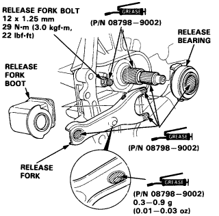
* Apply grease to the parts as shown, then install the release fork and release bearing.
NOTE: Use only Super High Temp Urea Grease (P/N 08798-9002).
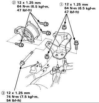
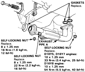
* Torque the mounting bolt and nuts in the sequence shown.
* Check that the bushings are not twisted or offset.
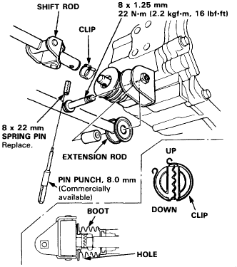
* Install the clip as shown.
* Turn the boot so the hole is facing down.
* Make sure the boot is installed on the shift rod.
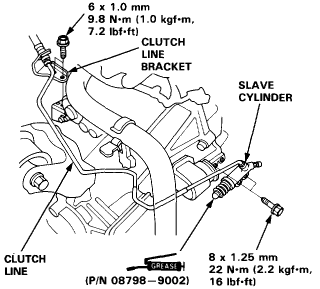
* Apply grease to the slave cylinder push rod.
NOTE: Use only Super High Temp Urea Grease (P/N 08798-9002).
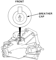
* Turn the breather cap so that the "F" mark points at the front of the car as shown.
* Refill the transmission with the recommended oil.
* Connect the positive (+) cable first, then the negative (-) cable to the battery.
* Check the clutch operation.
* Shift the transmission and check for smooth operation.
* Check the front wheel alignment.
Last edited by Barefoot; 09-19-2009 at 01:39 PM.
- Replacing clutch disk
Tags for this Thread
 Posting Permissions
- You may not post new threads
- You may not post replies
- You may not post attachments
- You may not edit your posts
-
Forum Rules


 Reply With Quote