I wrote this for a Chevy forum I was on, but basic cam info for any engine. All my pics are gone, Ill work on replacing them slowly.
The LS1 like any other engine works as a system, treat is as one, you want to get as much air in and out as you can. The plethora of mods out there will allow you to do that. Things to consider before you start on your modding process:
1) There is no "best" part when it comes to mods.
2) When you want to start modding your car come up with a tangible plan.
3) Do not go into modding blindly; you will end up wasting money, time, and effort.
4) Do your research before you buy mods.
5) Find out your states/counties emissions requirements before choosing mods
6) Be realistic on what your going to do with your car
7) Usable power under the curve is what you want to shoot for, do not just look at peak gains
8) Work within your budget
9) If your are still under warranty Contact your own dealership and discuss your warranty and modding issues.
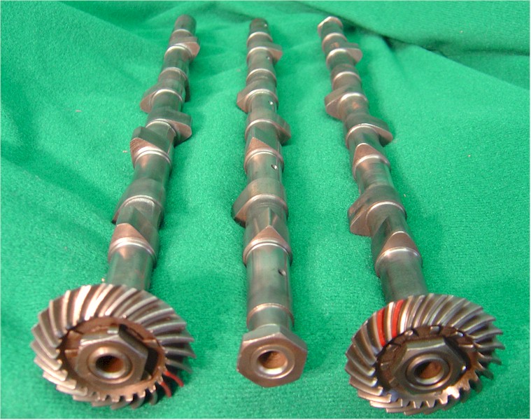
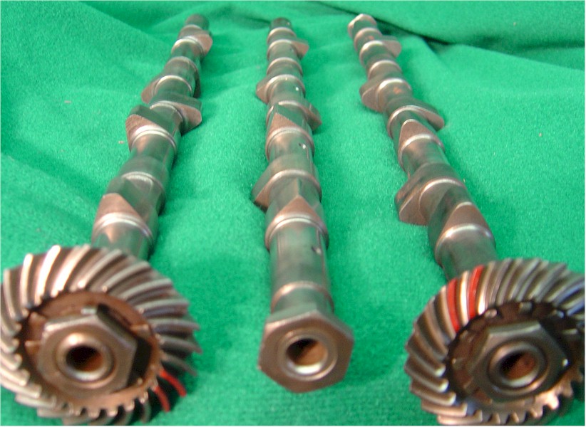
A. Cams
What they are:
What they do: Cams are the "brain" of your engine and dictate how your engine will perform; power, idle quality, valve events, ect.
What to look for:
- Get a basic understanding of cams before purchasing. It'll also help you understand the info/advice that is given on the boards.
- ALL gains are relative to your own setup
1) For example if you installed S2 heads and a tsp231 cam and only put down 390rwhp tuned don't fret if you started with a base of 290rwhp.
- When researching cams look at the average gains. Don't look at the highest gains you see (395rwhp with say and ls6 cam) and expect to get the same results when the average is 360-380rwhp depending on setup
- Can a cam be your first mod; yes. Should a cam be your first mod; NO.
1) Cams need to breath, that means a complete intake and exhaust setup. The bigger the cam the more prevalent those mods become.
2) A4 guys; match your stall and cam appropriately
- Don't be afraid of older or smaller cams (T1/B1, tr220, comps 218, ect). They might not use the latest and greatest lobe technology or break speed records but they are proven cams and are great for the guys looking for 400 > * rwhp cam only.
- Take Internet reviews of cams with a grain of salt and use them as reference only. Contact your local fbody club or ask around your local regional forum and find as many guys who have cams as you can. Hear and drive/ride along with as many different cam setups as you can. The reason for this is everyone has there own idea of what streetable is since that is a RELATIVE term. Decide on your own what streetable is to you
- Don't let someone talk you into a cam if it doesn't meet your requirements and fit your specific applications and goals.
- Keep in mind there is more then one way to make the same amount of power
- If you have the sniffer for emissions either go with the cam of your choice and pray you find a good enough tuner and have luck on your side or choose a smog friendly grind. Keep the overlap in check, the more negative overlap @ .050 the easier it will be to pass. Here is Ed's (Ed Vert's) Cali smog sheet from his tr224 114 which has negative 4* overlap @ .050.
- When buying a used cam ask for the cam card and/or serial numbers. Take that serial number and email or PM the company or board representative with that serial number. They will be able to tell you if in fact it is one of there grinds and if it's the one you had planned on purchasing. That is the only way short of having the cam spec'd on a cam doctor to know exactly what cam you are buying. Here's the serial number from my old TR230.
- Don't get caught up in peak HP. These are ls1 boards not Honda boards . Under the curve power is where it's at.
- To make things easier most sponsors offer cams as a package deal that includes all that you'll need for an installation. Here was my old cam kit.
I. Cam Overview:

-
- Your starting point:
Stock 98-00 trans am cam
[email protected] 198.86 intake 209.25 exhaust
Lift .498 intake .497 exhausts
LSA 119.45
Stock 01-02 trans am cam
[email protected] 196.37 intake 208.72 exhaust
Lift .464 intake .479 exhausts
LSA 115.92
When buying a cam it comes with a cam card. This card gives you the exact specs of the cam. Here is an MTI/Lunati T1 cam card and a LGM G5X2 cam card.
A. Duration:
- The amount of time (in degrees) that lift is generated is called the duration of the lobe. Camshafts operate at half engine speed. This is easy to see because the gear that turns the camshaft is twice the diameter of the crank gear that drives it. That means that the cam spins at half engine speed. Because of this, camshaft duration is always expressed in crankshaft degrees. This makes it easy when it comes time to degree the cam to ensure it is positioned accurately in the engine.

 Reply With Quote