Why?
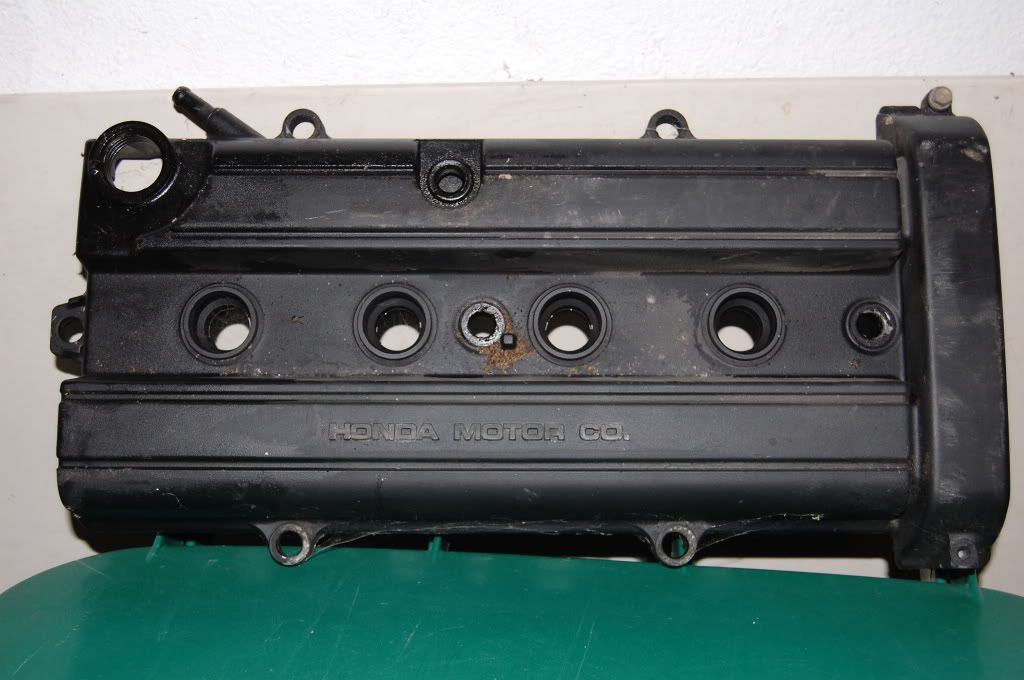
When venting your valve cover, you help release pressure that is built up in your crankcase. Excess crankcase pressure can led to blow-by, seals popping, and a reduction in power. When doing LSVtecs/B20Vtecs and using an obd2 block, you loose the capability to release some of that crankcase pressure through the PCV system, and must make up for the lack of having one. You can release this pressure two ways, through the block or the head. I'm currently doing both.
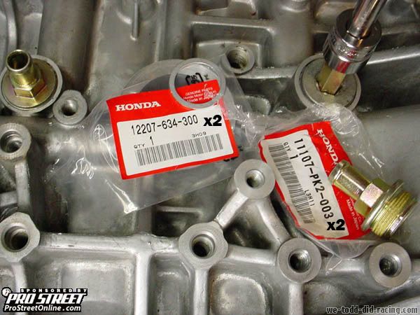
Parts needed for an AN Stainless Steel catch can setup.
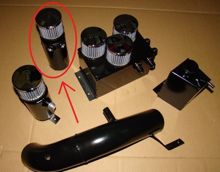
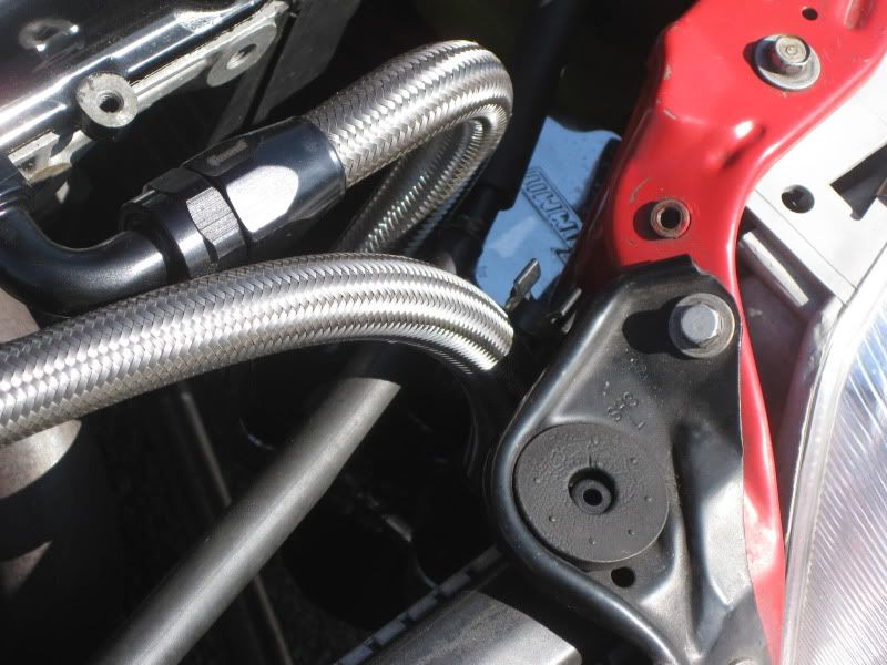
1-Catch Can
This is the one I’m using (circled)
It has two female ½ NPT fitting welding on the side, and one at the bottom for draining oil. (The fitting will depend on where you purchase the catch can from or what you decide to use if you made your own.) The inside must be baffle to allow the oil and flumes to separate.
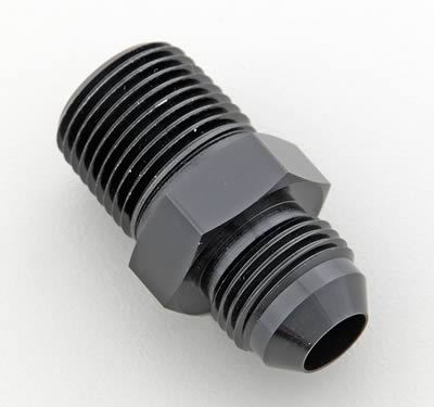
2- AN to Male NPT Adapter Fitting
This part may not be applicable to every setup. I needed this because my catch can require I convert my ½ NPT fittings to –10AN fittings.
(Part# SUM-220047 for red/blue, add B to the end for black)
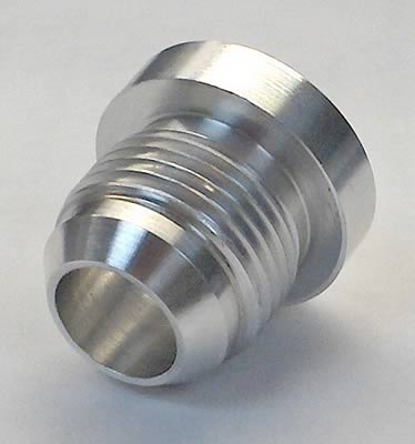
2-Weld-on Bungs
I decide to use -10AN bungs on my valve cover
Most people use -8AN, -10AN, or -12AN (there are people that use bigger ones, but I doubt they would apply to someone here). The rule of thumb, is the larger the better. Larger diameter bung would cause your catch can to less likely fill up with oil. Why? Because with larger bungs the velocity of the flumes is slower and less likely to carry oil with it. (Part# SUM-220063)
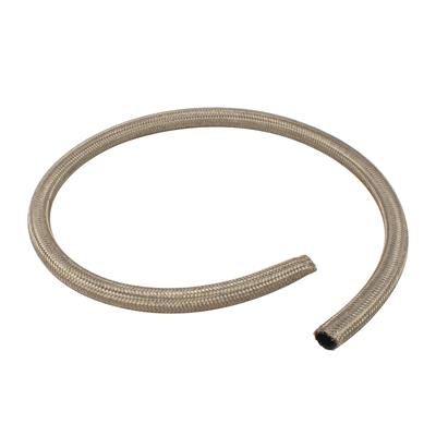
Stainless Steel Line (length depends on the placement of your catch can)
Order the lines based on what bungs you are using. I welded -10AN bungs on my valve cover, so I got -10AN SS lines. The length you need depends on where you’re placing the catch can. I order two 3ft lines (Part# SUM-230003)
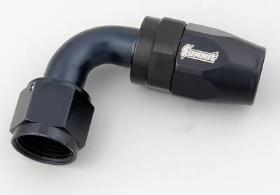
2-90degree bends
Once again get 2 90degree bends based on your hose size. I’m using -10AN so I got -10AN 90degree bends. One end is going into the SS hose, and the other end will be screwed down to the bungs on the valve cover (Part# SUM-220087 for red/blue, add a B at the end for black)
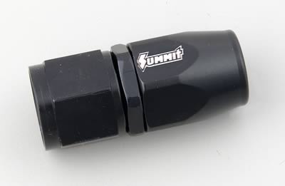
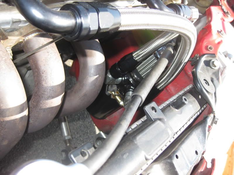
2- Hose Ends
Once again get the hose ends based on your hose size. One side is going to the hoses, the other end is getting screwed on to Male NPT Adapter Fitting that I screwed into my catch can. (Part# SUM-220090 for red/blue, add a B at the end for black)
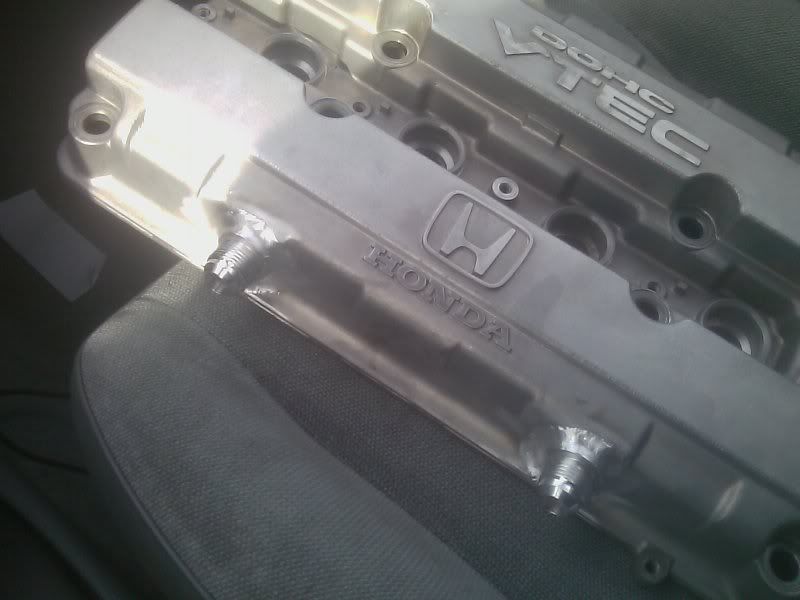
Assembly
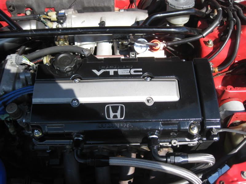
To attach the bungs to your valve cover, you must strip the paint where the bungs go. Then you must “TIG” weld the bungs to the valve cover. Whatever location you weld your bungs to make sure you the OEM baffle is covering the area. Now drill holes, making sure you don’t drill through the baffle.
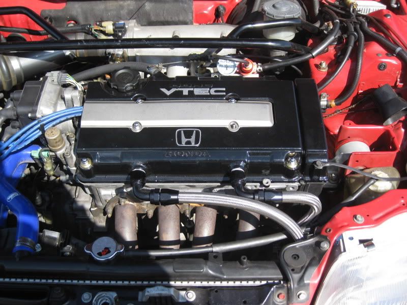
Results
To cut and attach the hose ends and 90degree bends, just mimic this link or video and your ready to attach the hoses to the valve cover and catch can.
http://www.honda-tech.com/showthread.php?t=2150049
http://www.youtube.com/watch?v=aDSozy6MZto
*edit*
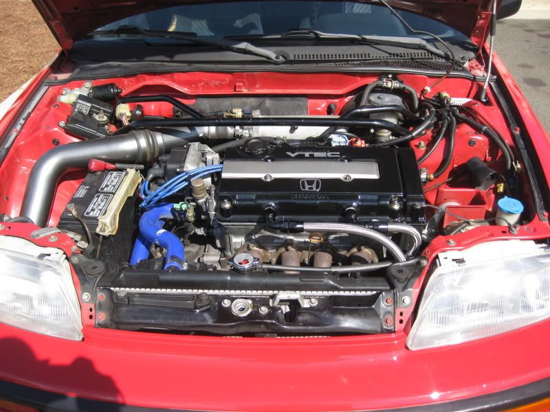
Here are the final results
Thanks to Blueridge Motorsports for the Catch Can, and DG Performance for TIG welding the bungs to the valve cover.
If I missed anything, just pm me and I'll add it to the post.

 Reply With Quote


 ...lol


 [/URL]